In 1995-96 six large fire tests, in all of which the internal steel beams were unprotected against heating, were carried out on a full-scale 8-storey composite building constructed in 1994 at the BRE Fire Research Laboratory at Cardington[6]. The test building was constructed as a typical office development, using downstand beams supporting lightweight slabs cast in-situ onto ribbed steel decking. Composite action was achieved between both primary and secondary steel beams and the floor slabs using through-welded shear studs.
The six fire tests were sited in different types and sizes of fire compartments designed to test a variety of situations. See the locations of the fire tests below:
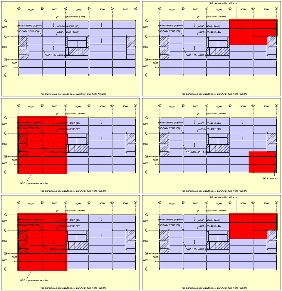
The floors were loaded throughout the testing period using sand-bags, which contributed to an overall floor loading of 5.48kN/m². For the secondary composite beams this equates to a load ratio of 0.44. The most significant qualitative observation was that in none of the six fire tests was there any indication of run-away failure, despite unprotected steel beam temperatures over 1000°C in some tests. Tensile membrane action in the concrete floor slabs may have played an important role in this respect. The ambient-temperature material properties used in the modelling, based on tested values from the Cardington frame where these were available, are as follows: · The yield strength of steel members is 308 N/mm² for Grade 43 steel (S275) and 390 N/mm² for Grade 50 steel (S355); · The yield strength of the steel used in the anti-crack mesh was assumed to be 460 N/mm²; · The elastic modulus of steel was N/mm²; · The average compressive strength of concrete test samples was 35 N/mm2 In all tests the internal steel beams in the ceiling of the compartment were left unprotected, although columns were mainly protected and in some tests the perimeter beams were protected. It is not possible to be totally certain of the conditions of these tests, because of inevitable variations in details such as loading, heating, slab thickness and material properties. Nevertheless they represent the most significant source of experimental data for steel structures in fire, and provide a unique basis for comparison with regard to complete structure behaviour.
Restrained Beam Test
The Restrained Beam Test involved heating a single 305x165UB40 secondary beam and an area of the surrounding slab on the seventh floor. The major objective of this test was to study the effects of restraint from a large area of surrounding cool structure, including floor slabs, on the behaviour of the heated structure. The finite element mesh layout used for the analysis of this test is shown opposite.
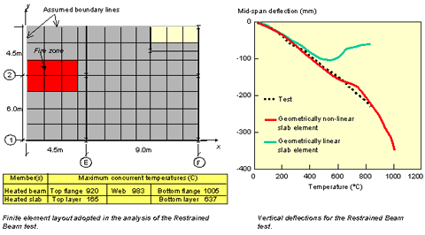
The temperature distributions in the steel beam and slab are based on the average values recorded. In order to investigate the structural behaviour up to extremely high temperatures, these temperatures have been extrapolated linearly. The test results (mid-span deflection against bottom flange temperature) are shown in the left-hand figure, together with the analytical results. The predictions of the present model, including geometric non-linearity of the slab element, are in remarkably good agreement with the test results, whereas using a linear slab element gives a poor representation above about 500°C.
British Steel Plane Frame Test
The plane frame test involved the beams and columns supporting the 4th floor across the full width of the structure. The two internal columns were fire-protected to 200mm below the lower flange of the 9m long 610x228x101UB primary beam. The maximum recorded temperatures in this test were 808°C (steel beam) and 385°C (concrete slab), whilst the top surface of the slab reached 95°C. These have been extrapolated linearly in order to investigate the structural behaviour of this fire test up to higher temperatures. The finite element mesh layout used for the analysis is shown below.

The protected cross-sections of columns are assumed to have uniform temperature, rising to a maximum of 600°C, while the unprotected columns lengths are at the same temperature as the beam bottom flanges. Comparisons of the Vulcan predictions against the test results at location D9 are shown in the figure, and indicate good agreement.
British Steel Corner Bay Test
This test was carried out on a corner bay of the structure 9.98m wide by 7.57m deep. All columns and perimeter beams were wrapped with ceramic fibre insulation, but all other structural elements were left unprotected. During the fire test the maximum recorded atmosphere temperature in the compartment was 1028°C, which occurred after 80 minutes. The finite element mesh layout used for the analysis is shown opposite. A single set of temperature distributions was assumed for all unprotected beams, with a different set for protected beams. Columns were assumed to be at uniform temperature, and the average test temperature distribution through the thickness of the concrete slab was used.
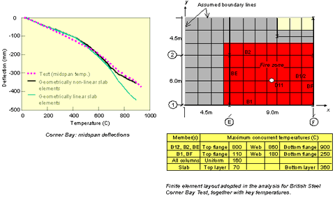
The graph above compares the test results with the predicted deflections at the mid-span (point D11) of the central secondary beam B1/2 against the bottom flange temperature. It can be seen that while the vertical deflections remain below 300mm, in which range the key temperature of the steel beam is less than 700°C, there is clearly little influence from tensile membrane action. On further increase of temperature the steel beams lose most of their strength, and the loads above fire compartment begin to be carried largely by the floor slab, increasingly in membrane action as the temperature rises, as can be seen in the sequence shown below.
The figure below shows the change in principal membrane tractions as steel temperature rises (length of vector shows the magnitude of traction, blue vectors are compression, red vectors are tension):

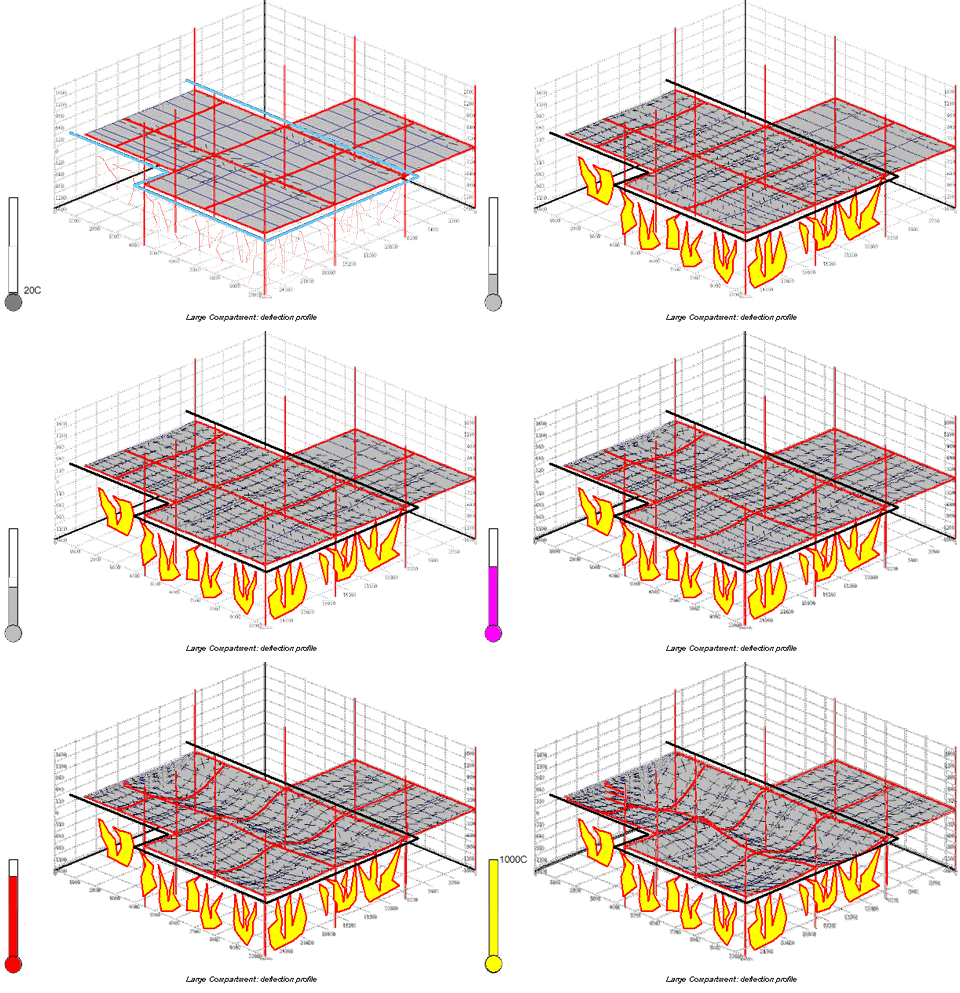
The deflection profile of the composite slab at 900°C, as given by the geometrically non-linear slab elements, is shown in here, including the cracking patterns of the top concrete layer.

BRE Corner Bay Test
The BRE corner bay test was similar in extent to that described above, although wind-posts effectively restricted vertical downward movement of the edge beams to 80mm. All of the steel beams in the compartment were left unprotected, but the steel columns inside the compartment were protected by insulating material up to the underside of the ceiling slab, including the beam-to-column connections. During the fire test the maximum recorded temperature were 1051°C (atmosphere), 842°C (internal beam), 590°C (edge beam), 285°C (concrete slab), and 150°C (columns). These have been extrapolated to allow structural analysis at higher temperatures. The finite element mesh layout adopted for the analysis is shown opposite.
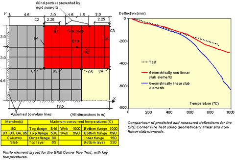
The comparisons between the predicted and test results for vertical deflection of the central position D19 are plotted in this figure. The geometrically linear results give a reasonable representation up to temperatures of about 600°C, but at higher temperatures are unable to model the behaviour of the floor slab adequately. In contrast, the geometric non-linear results provide a very good comparison throughout.
The development of the principal membrane tractions in the BRE corner test can be seen below (length of vector shows the magnitude of traction; blue vectors are compression, red vectors are tension).
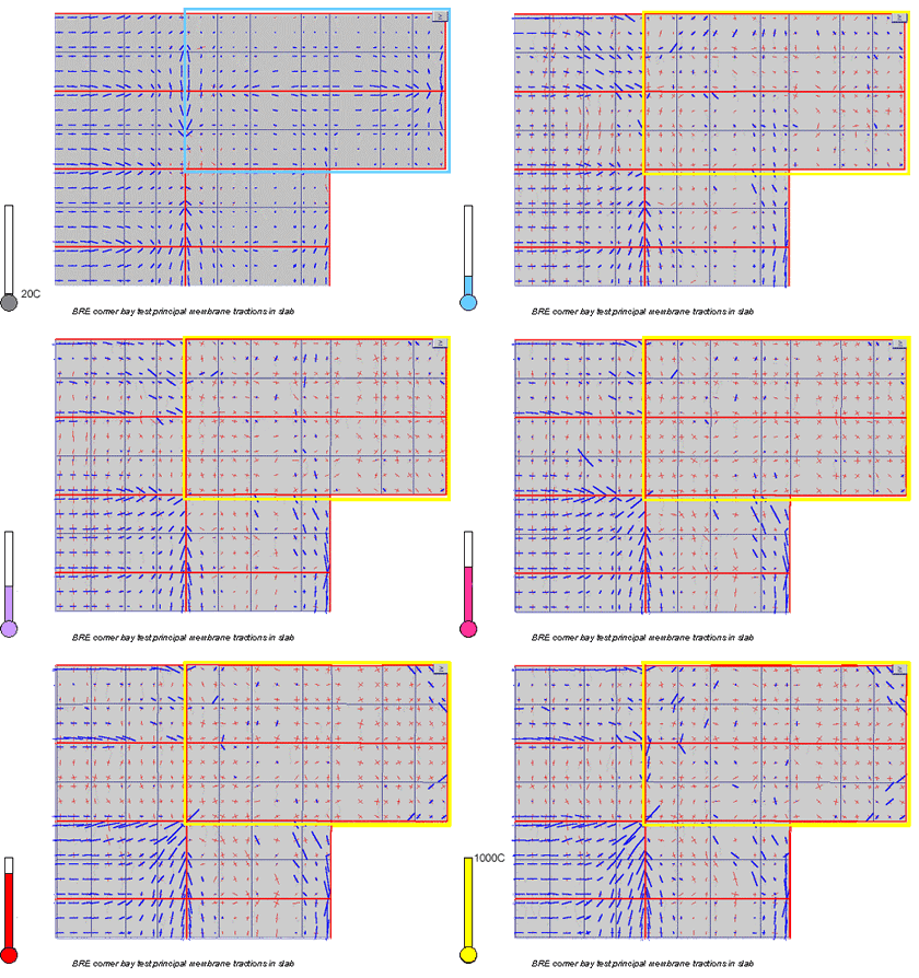
The principal tractions shown in the BRE corner bay do not appear to show classic membrane action, since there is no apparent “ring” of compressive stress around the periphery of the slab. This is explained by the graph showing the development of axial force in the steel beams around the edges of the heated slab in each case.
In the BS test the edge members stay in tension throughout, and eventually all the members surrounding the slab have low axial forces. In the BRE test the peripheral members retain high compressive forces until the end of the test, so the compressive “ring” still exists but is located mainly in these beams.

The different behaviour of the peripheral beams can be traced back to their protection and support conditions in the two tests. In the BS test the edge beams were protected but not externally supported. In the BRE test the edge beams were supported but left unprotected so that the high compressive forces in these members are due to their restrained expansion against the attached slab. This also keeps the slab in tension over the edge beams.
BRE Large Compartment Test
The BRE large compartment test extended across the full width of the building, between Grid-line A and a line 0.5m from Grid-line C, covering an area of 340m2. All the internal steel beams were unprotected, but the columns were protected over their full height, including the connections. This fire test was rather cooler than the others, having maximum recorded atmospheric and steelwork temperatures of 763°C and 691°C, respectively. The maximum average measured temperature of the bottom layer of the concrete slab was about 260°C. These have been extrapolated linearly in order to investigate the structural behaviour up to higher temperatures. The finite element mesh layout adopted for the analysis is shown below.


The comparisons between the predicted and test results for vertical deflections at key position D32 are shown above. It can be seen that the predictions are in good agreement with test results over the test temperature range.
The deflection profile of the composite slab, given by the Vulcan modelling, can be seen from the figure below, at unprotected steel temperatures from 20°C to 1000°C, including the cracking patterns of the top layer of concrete. The figure below shows the deflection pattern as steel temperature rises:
British Steel Office Fire (Demonstration) Test
The demonstration test was designed to represent a typical office fire, and was less thoroughly instrumented than the others. The internal column and the internal surfaces of perimeter columns were fire-protected to their full height, including the connections, with a 25mm thickness of ceramic-fibre blanket. However, all the beams and the beam-to-beam connections remained totally exposed.

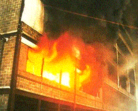

The maximum temperatures recorded were 1213°C (atmosphere) and 1150°C (steel beams). No temperature data was recorded for the floor slabs. Due to the high variation in the recorded temperatures of the steel beams, the Vulcan analysis used the actual test temperatures of individual beams, and results are plotted with respect to time. The temperature of the floor slab was assumed to follow a similar pattern to that in the BRE Corner-Bay Test, although it is acknowledged that temperature gradients may be rather different. The finite element mesh layout adopted for the analysis is shown below.
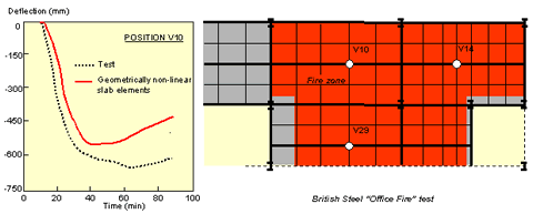
The analytical predictions for deflection against test time at key positions V10 are compared with the test results above, and show reasonable comparison, given that slab temperature profiles have to be assumed in the analyses. Note that in this test there is some evidence that, after 35 minutes of the test, the slab had deflected sufficiently to come into contact with the fire compartment wall close to position V29 and this may have significantly influenced the recorded test behaviour.
